Mobility batteries must deliver current without excessive voltage drop, heat, nuisance protection trips, or accelerated aging. The correct design is a system decision involving cells, BMS, conductors, thermal paths, enclosure, charger, and vehicle load.
Define continuous, peak, and regenerative current
Average current alone is not sufficient for traction applications. Startup, hill climbing, acceleration, stall conditions, accessories, and regenerative charging can create different electrical limits.
The design team should define current magnitude and duration, minimum pack voltage, controller cut-off, duty cycle, ambient temperature, and expected state of charge during the event.
Select cells using resistance and thermal behavior
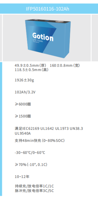
A cell with adequate capacity may still be unsuitable if its internal resistance creates too much voltage sag or heat. Cell evaluation should consider discharge curves, temperature rise, cycle performance, matching, and behavior at low state of charge.
Parallel configuration reduces current per cell, but it also affects pack size, weight, fault current, busbar design, and production matching requirements.
Coordinate the BMS with the vehicle controller
The BMS needs current sensors, MOSFETs or contactors, protection thresholds, delay times, balancing, temperature monitoring, and communication suited to the vehicle. Protection settings should distinguish a valid short circuit from a permitted acceleration pulse.
Controller and charger limits should be coordinated with the battery so one component does not repeatedly drive another into protection.
Design low-resistance current paths
Busbars, nickel or copper connections, cable gauge, connector rating, terminal hardware, welding, and fastening torque all influence resistance. Small losses become significant at high current because heating increases with the square of current.
Mechanical retention is equally important. Vibration, shock, and repeated service can loosen connections or stress cells if the structure is not designed for the vehicle environment.
Validate the complete pack under realistic loads
Testing should include representative acceleration, grade, continuous driving, low state of charge, hot and cold conditions, charging, regenerative events, and protection behavior. Temperature should be measured at cells, busbars, BMS power components, connectors, and other likely hot spots.
The result should be evaluated against performance margin, not only whether the pack completed one test.
| Subsystem | Engineering focus | Validation example |
|---|---|---|
| Cells | Resistance, current capability, matching, cycle life | Load profile and temperature-rise test |
| BMS | Thresholds, sensing, power devices, communication | Peak current and fault response |
| Conductors | Busbars, cables, connectors, joints | Voltage-drop and thermal scan |
| Mechanical system | Retention, vibration, enclosure, service | Vibration, shock, and installation review |
Do not size a mobility pack from amp-hours alone. Current duration, voltage sag, heat, and protection coordination determine whether the pack can power the vehicle reliably.
Related battery resources
Continue from the technical overview to relevant VTCBATT product and engineering resources.
Frequently asked questions
Why does a battery voltage drop under acceleration?
Cell and connection resistance create voltage drop as current rises. State of charge and temperature also affect the amount of sag.
Should the BMS rating equal the motor rating?
The correct BMS rating depends on the actual battery current profile, controller behavior, peak duration, regenerative current, and protection strategy.
What is the most important thermal test?
A representative full-system load test is essential because it reveals combined heating in cells, conductors, connectors, and BMS components.