Technical insight
Product and application details
IoT Devices and GPS Tracking
The compact 9mm thickness allows seamless integration into space-constrained tracking modules without adding bulk.

portable monitors
Its 3.7V nominal voltage aligns perfectly with standard single-cell display driver requirements for consistent brightness.

remote control (RC) model boats
Operating reliably in -20℃ temperatures ensures stable performance during cold water operations where other batteries fail.

remote control (RC) Space Shuttle
Lightweight at only 35.5g, it minimizes payload weight to maximize flight duration and maneuverability for models.

remote control (RC) vehicles
The 1500mAh capacity provides sufficient runtime for moderate off-road driving sessions before requiring a recharge.

wireless game controllers
Slim 52mm dimensions fit comfortably within ergonomic controller grips, maintaining a low profile for user comfort.
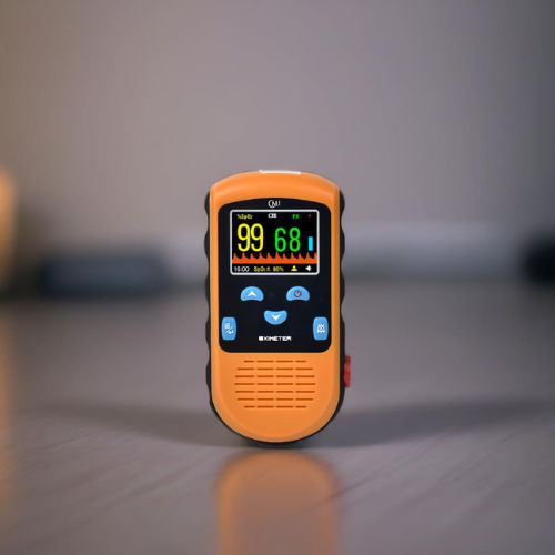
Medical Portable or Desktop Pulse Oximeter
Stable 3.7V output ensures accurate sensor readings by preventing voltage drops during critical measurement cycles.

Portable Electric Equipment
Standard 0.5C discharge rate supports steady power delivery for low-drain portable gadgets without overheating the cell.
VTCBATT Polymer Li-Ion Battery Specifications Model: VTCBATT 903450HT Capacity: 1500mAh | Voltage: 3.7V 1. Visual Inspection Any visual inspection defects will affect the electronic characteristics, such as leakage, flaw, are not in existence. 2. Charge/Discharge Methods and Test Conditions No. Item Testing Condition and Method 1 Charging Current Quick CC: 0.5C 5 A Standard CC: 0.2C 5 A 2 Standard Charging Constant Current Charging at 0.2C 5 A to 4.2V. Constant Voltage Charging at 4.2V to cut-off current ≤ 0.01C 5 A 3 Quick Charging Constant Voltage Charging at 4.2V to cut-off current ≤ 0.01C 5 A 4 Standard Discharge
VTCBATT
Polymer Li-Ion Battery Specifications
Model: VTCBATT 903450HT
Capacity: 1500mAh | Voltage: 3.7V
1. Visual Inspection
Any visual inspection defects will affect the electronic characteristics, such as leakage, flaw, are not in existence.
2. Charge/Discharge Methods and Test Conditions
| No. | Item | Testing Condition and Method |
|---|---|---|
| 1 | Charging Current | Quick CC: 0.5C5A Standard CC: 0.2C5A |
| 2 | Standard Charging | Constant Current Charging at 0.2C5A to 4.2V. Constant Voltage Charging at 4.2V to cut-off current ≤ 0.01C5A |
| 3 | Quick Charging | Constant Voltage Charging at 4.2V to cut-off current ≤ 0.01C5A |
| 4 | Standard Discharge | Constant discharge at 0.2C5A to cut-off voltage of 3.0V. |
| 5 | Charging Time | Standard charging time: 6.5 hours Quick charging time: 2.5 hours |
| 6 | Temperature & Humidity | Standard charging: 0~45℃, 45~85%RH Quick charging: 10~35℃, 45~85%RH Standard discharging: -10~60℃, 45~85%RH |
| 7 | Open Voltage | 3.75~3.95V (Before shipping) |
3. Mechanical Characteristics
| No. | Item | Testing Condition and Method | Standard |
|---|---|---|---|
| 1 | Vibration Testing | After standard charging, fixed the cell to vibration table and subjected to vibration cycling that the frequency is to be varied at the rate of 1Hz per minute between 10Hz and 55Hz, the excursion of the vibration is 0.38mm. The cell shall be vibrated for 30 minutes for three axis of XYZ axes. | No leakage. Left Capacity ≥ 90%, after 3 hours. |
| 2 | Fall Down Testing | Drop the cell from 1 meter height onto the concrete ground twice. | No explode, no fire and no leakage |
4. Safety Testing
| No. | Item | Testing Condition and Method | Standard |
|---|---|---|---|
| 1 | Over-charge | Charge is conducted for 8 hours while the invariable voltage is 4.6V. | No deformation and leakage |
| 2 | Short-circuit | The charged battery is short-circuited for 1 hour at 100mΩ. | No explode or fire |
| 3 | Heat Shock | Put the battery into the heat box, the temperature is rising to 130±2℃ at the rate of (5±2℃)/min and maintain for 10 minutes. Then cool down to room temperature at the rate of 5±2℃/min. | No explode or fire |
| 4 | Humidity and Heat | Put the charged battery into box for 48 hours, the temperature is 40±2℃ and the relative humidity is 90%~95%. | No smoke or explode |
5. Temperature Testing
| No. | Item | Testing Condition and Method | Standard |
|---|---|---|---|
| 1 | High Temperature | Put the charged battery into the high temperature box for 2 hours at 55±2℃. And discharge the battery at 1C current until the voltage is 3.0V. | Discharge 90% of the original capacity. |
| 2 | Low Temperature | Put the charged battery into the low temperature box for 16 hours to 24 hours at -10±2℃. And then discharge the battery at 0.1C until the voltage is 3.0V. | Discharge more than 45% of the original capacity. |
6. Electricity Maintenance
| No. | Item | Testing Condition and Method | Standard |
|---|---|---|---|
| 1 | Electricity Maintenance | Reset the charge battery for 28 days at the ambient temperature of 25±0.5℃. And then discharge the battery until the voltage is ended. | Discharge more than 85% of the original capacity. |
7. Storage and Others
Should the batteries have been stored for 3 months and stay unused, then it is advisable to transfer them to a dry and cool place. Voltage at storage should be between 3.75V and 3.95V and the storage conditions followed as item 1.
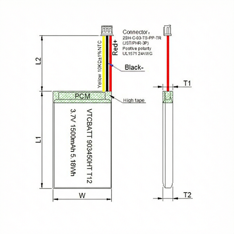
8. Mechanical Drawings
8.1 Assembly Diagram (not in scale)
| Item | Description | Dimension (mm) |
|---|---|---|
| T1 | Thickness | 9.2 MAX |
| T2 | Thickness | 9.0 MAX |
| W | Width | 34.5 MAX |
| L1 | Length | 52.0 MAX |
| L2 | Lead wire length | 60±3 |
Connector model: 2SH-C-03-TS-PP-TR (JST/PHR-3P)
8.2 Single Cell Drawing (not in scale)
| Item | Description | Dimension (mm) |
|---|---|---|
| T | Thickness | 9.0 MAX |
| W | Width | 34.0 MAX |
| L | Length | 50.0 MAX |
| L2 | Length | 0.2~2.0 |
| L3 | Length | 5~10 |
| L1 | Length | 4~5 |
| W2 | Center distance | 18.5±1.5 |
| d | Width | 3.0±0.2 |
9. Handling Precaution and Guideline for Li-Polymer Rechargeable Batteries
This document of ‘handling precautions and guideline for rechargeable batteries’ shall be applied to the battery cells manufactured by VTCBATT. It is advisable to contact VTCBATT in advance if and when the customer needs other applications of operating conditions than those described in this document. Additional experimentation may be required to verify performance and safety under such condition. VTCBATT will take no responsibility for any accident when the cell is used under other condition. VTCBATT will inform, in a written form, the customers of improvement(s) regarding proper use and handling of the cell, if it is deemed necessary.
1. Charging
1.1 Charging Current: Charging current should be less than maximum charge current specified in the Specification Approval Sheet.
1.2 Charging Voltage: Charging voltage should be less than the maximum nominal voltage 4.2V, and the charging voltage upper limit is 4.30V (single pack).
1.3 Charging Temperature: The cell should be charged within the range specified in this Specification Approval Sheet.
1.4 Notes: Since charging with constant current or constant voltage, reverse charging is prohibited. In case of the cell is connected improperly, the cell cannot be charged. Simultaneously, the reverse charging may cause damaging to the cell which may lead to degradation of cell performance and damage the cell safety, and could cause heat generation or leakage.
2. Discharging Current
The cell shall be discharged at less than the maximum discharge current specified in the Specification Approval Sheet. High discharging current may reduce the discharging capacity significantly or cause over-heat.
3. Discharging Temperature
Discharging Temperature should be within the range specified in this Specification Approval Sheet.
4. Over-Discharge
Over-discharging will cause cell low-performance and function loss. The cell would be in an over-discharged state by its self-discharge characteristic. In order to prevent over-discharging, the cell shall be charged periodically to maintain between 3.75V and 3.95V.
5. Protective Circuit Module (PCM)
5.1 The cell/battery pack shall be with a PCM that can protect cell/battery pack properly. PCM shall have functions of:
- Overcharge prevention
- Over-discharge prevention
- Over current prevention to maintain safety and prevent significant deterioration of cell performance. The over current can occur by external short circuit.
5.2 Overcharge Protection: Overcharging prevention function shall stop charging if any cell of the battery pack reaches 4.30V.
5.3 Over-discharge Protection: Over-discharging protection function shall monitor the voltage of every cell in the pack.
6. Storage
Cells should be stored in proper temperature specified in datasheet.
10. Notice
10.1 Handling of Cells
- Avoid any short-circuit; it will cause the pole hot and lost electronic functions.
- Soft packing is very damaged by sharp edge parts such as needles and knives. Avoid cells touch with sharp edge part, when handling and storage.
- Besides the poles is the sealed edge. Don’t bend or fold dealing edge, for it is a sensitive part.
- Don’t open the folding edge on both sides of the cells.
- Don’t bend the tabs, for the tabs are not so stubborn.
- Avoid mechanical shock to the cells.
- Don’t put the cells into the heater, washing machine or high-voltage container.
- Don’t use the charger without any safety guarantee, and recommend you use specified charger.
- You should immediately stop charging, as cell is overheating, delivery any smell, changed color, distortion etc.
- Before children use batteries, adults should explain the usage first.
- Before use batteries, please read the handling guideline carefully and fully understand.
- Away from the static-electronic field, while using, charging and storing cells.
- Don’t put the cells together with metal conductors such as chains, barrette, bolt into the pocket or stored them together.
- Don’t use metal conductor to short cut the positive and negative poles.
- Don’t mis-assemble the positive pole with the negative one.
10.2 Notice for Designing Battery Pack
10.2.1 Package Design
- Battery pack should have sufficient strength and battery should be protected from mechanical shock.
- No sharp edge components should be inside the pack containing the battery.
10.2.2 PCM Design
- The overcharge threshold voltage should not exceed 4.25V (single pack)
- The over-discharge threshold voltage should not be lower than 2.40V (single pack)
- The PCM should have short protection built inside.
10.3 Notices for Assembling Battery Pack
10.3.1 Tab Connection
- Ultrasonic welding or spot welding is recommended to connect battery with PCM or other parts.
- If apply manual solder method to connect tab with PCM, below notice is very important to ensure battery performance:
- The solder iron should be temperature controlled and ESD safe.
- Soldering temperature should not exceed 350℃.
- Soldering time should not be longer than 3 seconds.
- Keep battery tab cool down before next time soldering.
- Directly heat cell body is strictly prohibited. Battery should be damaged by heat above approx. 60℃.
10.3.2 Cell Fixing
- The battery should be fixed to the battery pack by its large surface area.
- No sharp edge at the assembling position.
- No cell movement in the battery pack should be allowed.
11. Others
- The disassembling may generate internal short circuit in the cell, which may cause gassing, firing, or other problem.
- Prohibition of Disposing Cells of Fire: Never incinerate or dispose the cells of fire, for these may cause burning of the cells.
- The cells should never be soaked with liquids such as water, drinks or oil.
- Prohibit using the cells mixed with different manufactories. Prohibit using new cells mixed with old ones.
Appendix: Electrical Characteristics
| Item | Symbol | Content | Criterion |
|---|---|---|---|
| Over Charge Protection | VDET1 | Overcharge detection voltage | 4.280±0.020V |
| tCU | Overcharge detection delay time | 0.7s~1.3s | |
| VREL1 | Overcharge release voltage | 4.180±0.05V | |
| Over Discharge Protection | VDET2 | Overdischarge detection voltage | 3.00±0.05V |
| tDL | Overdischarge detection delay time | 179.2ms~332.8ms | |
| VREL2 | Overdischarge release voltage | 3.00±0.1V | |
| Over Current Protection | VDET3 | Overcurrent detection voltage | 0.18±0.010V |
| IDP | Overcurrent detection current | 4±1A | |
| tIOV1 | Overcurrent detection delay time | 11.2ms~20.8ms | |
| – | Release condition | Cut load | |
| Short Protection | – | Detection Condition | Exterior short circuit |
| – | Release condition | Cut short circuit | |
| tIOV2 | Short circuit detection delay time | 196~364μS | |
| Interior Resistance | RDS | Main loop electrify resistance | VC=4.2V, RDS ≤ 44mΩ |
| Current Consumption | IDD | Current consume in normal operation | 4μA Type, 7.0μA Max |
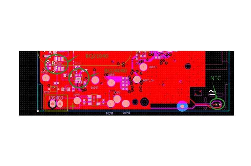
BOM of PCB
| No. | Location | Part Name | Specification | Package | Qty | Supplier/Remark |
|---|---|---|---|---|---|---|
| 1 | U1 | Protection IC | S-8261DAI-M6T1U | SOT-23-6 | 1 | SEIKO |
| 2 | U2 | MOSFET | S8205A | TSSOP-8 | 1 | DP |
| 3 | R1 | Resistor | SMD 330Ω±5% | 0603 | 1 | |
| 4 | R2 | Resistor | SMD 470Ω±5% | 0603 | 1 | |
| 5 | R3 | NTC | SMD 10kΩ±5% B=3435±5% | 0603 | 1 | |
| 6 | C1 | Capacitor | SMD 0.1uF/25V | 0603 | 1 | |
| 7 | PCB | PCB | 26×3.8×0.6mm, FR-4 (L×W×T) | / | 1 |
Product Modified Record List
| Version | Date | Mark | Modified Content | Approved By |
|---|---|---|---|---|
| C1.0 | 2018.5.3 | – | The first release | Robert Zhou |
| C1.1 | 2019.11.30 | – | Change to high temp battery | Robert Zhou |
| C1.2 | 2019.12.5 | Add NTC | Add NTC | Robert Zhou |