Technical insight
Product and application details
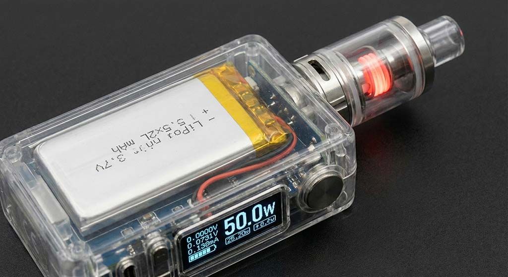
Box Mod
Its 5.2mm thickness allows this battery to fit into slim box mod chassis while delivering steady 3.7V power.
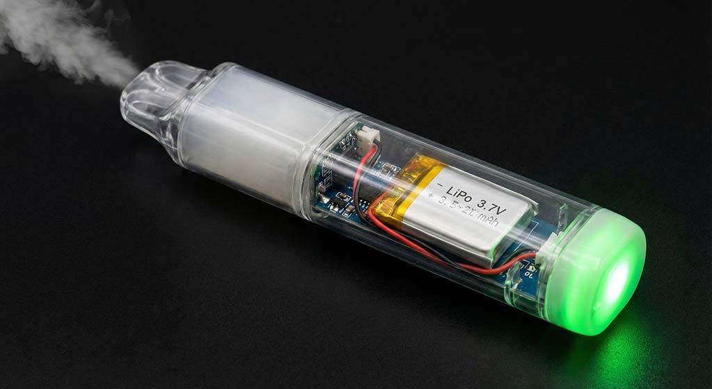
Disposable Vape
The 200mAh capacity provides sufficient energy density for disposable vape devices without adding excessive weight to the unit.
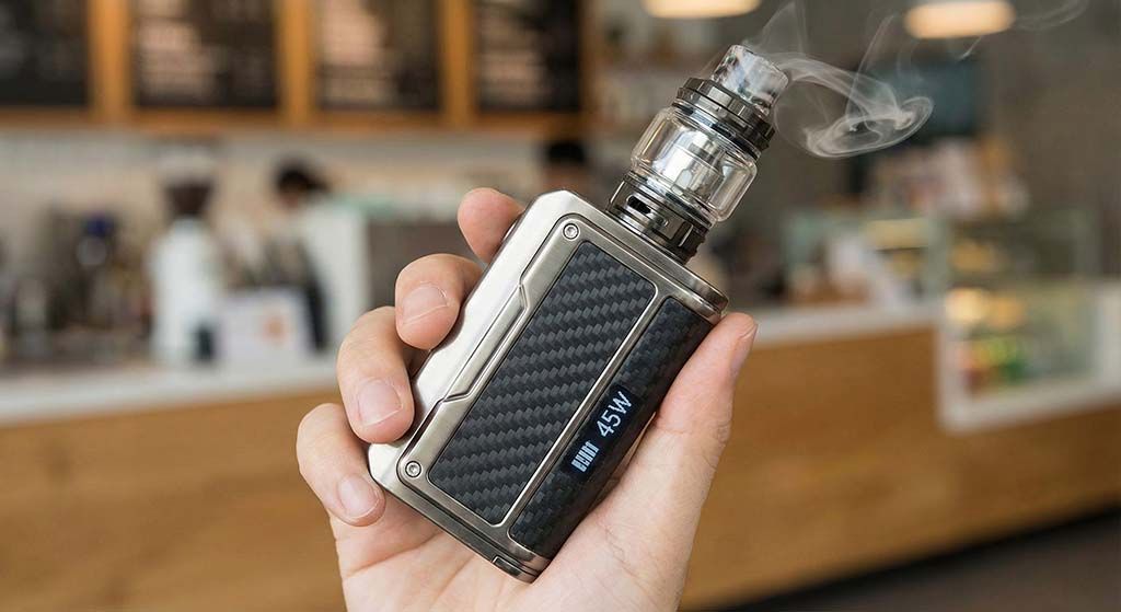
handed box mod
Weighing just 3.8g, this lightweight cell reduces hand fatigue during extended vaping sessions in handheld box mod devices.
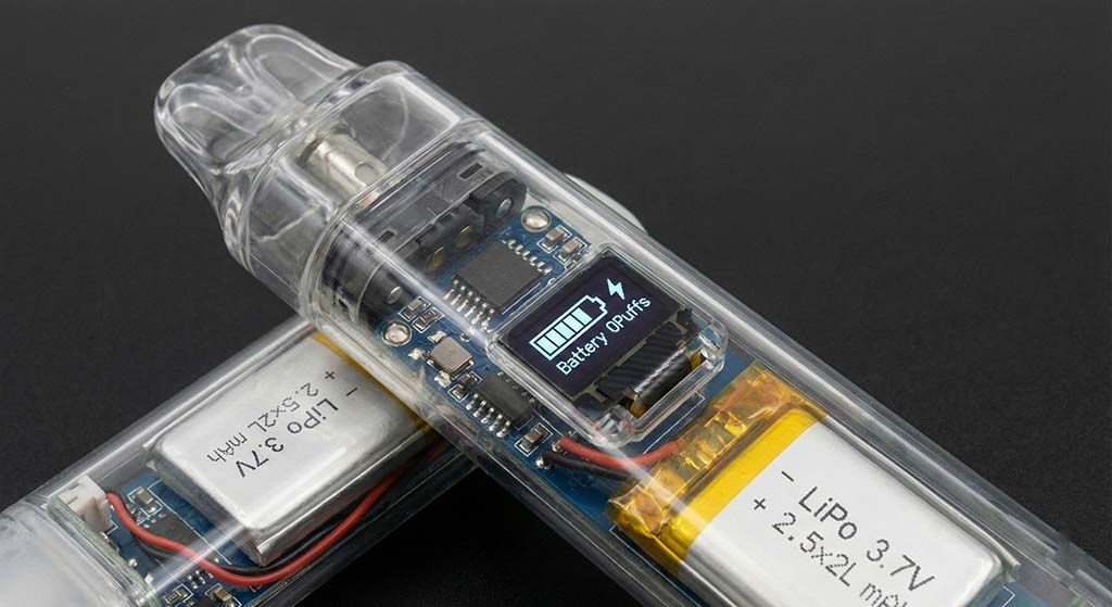
Slim Pod System
With dimensions of only 5x20x25mm, this compact LiPo battery fits tightly into space-constrained slim pod systems.
Model: VTC-LP502025 3.7V 200mAh Lithium-ion Polymer Rechargeable Battery High-performance rechargeable LiPo cell engineered with high-density chemistry. Featuring integrated Seiko protection IC and dual MOSFET safety circuits, customized for wearable medical devices, smart IoT tags, GPS trackers, and premium microelectronics. Product Visual Representation 1. Scope & Product Specification This technical datasheet describes the parameters and testing standards for the Li-ion Polymer Rechargeable Battery, model VTC-LP502025 , manufactured and supplied by VTC Power Co., Ltd. Designed with standard B2B commercial reliability, this cell features high safety levels, excellent discharge rate stability, and deep cycle longevity. VTC Power offers complete customization including PCM

1. Scope & Product Specification
This technical datasheet describes the parameters and testing standards for the Li-ion Polymer Rechargeable Battery, model VTC-LP502025, manufactured and supplied by VTC Power Co., Ltd.
Designed with standard B2B commercial reliability, this cell features high safety levels, excellent discharge rate stability, and deep cycle longevity. VTC Power offers complete customization including PCM circuit tuning, wire length customization, NTC thermal resistor integration, and standard connector terminations.
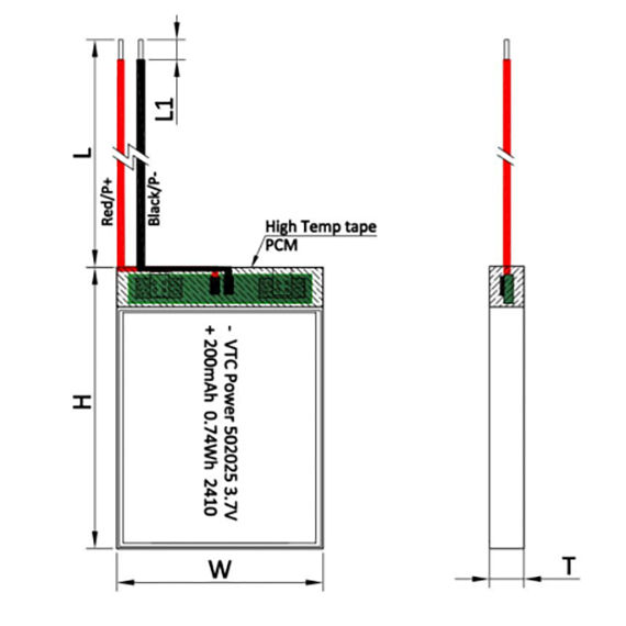
2. Drawing of Cell & Battery Pack Dimensions
Mechanical dimensions define the cell parameters and battery pack constraints. Standard tolerances apply.
| Item | Description | Specification / Dimension |
|---|---|---|
| A | Cell Tab Length | 4 ~ 8 mm |
| B | Cell Tab Pitch | 7.5 ± 1.5 mm |
| C | Cell Tab Width | 2 ± 0.2 mm |
| D | Cell Top Sealant Length | 5 ± 1 mm |
| T (Cell) | Cell Thickness (Max) | Initial: 5.0 mm | After 500 cycles: 5.4 mm |
| W (Cell) | Cell Width (Max) | 20.0 mm |
| H (Cell) | Cell Height (Max) | 25.0 mm |
| T (Pack) | Battery Pack Thickness (Max) | 5.2 mm |
| W (Pack) | Battery Pack Width (Max) | 20.5 mm |
| H (Pack) | Battery Pack Height (Max) | 27.0 mm |
| L | Wire Length | 20 ± 3 mm (UL1571 30AWG) |
3. Basic Performance Specifications
All parameters are measured at a standard temperature of 15~35°C, relative humidity 45~85%RH, and atmospheric pressure of 86~106KPa.
| NO. | Technical Parameter | Specification Value | Test Conditions / Notes |
|---|---|---|---|
| 1 | Rated Capacity | 210 mAh | 0.2C discharge to 3.0V |
| 2 | Nominal Capacity | 200 mAh | 0.2C discharge to 3.0V |
| 3 | Minimum Capacity | 190 mAh | 0.2C discharge to 3.0V |
| 4 | Weight | ≈ 3.8 g | Approximate cell weight |
| 5 | Initial Impedance | ≤ 350 mΩ | 3.7V AC 1KHz measured |
| 6 | Nominal Voltage | 3.7 V | Standard operating voltage |
| 7 | Initial Voltage | ≥ 3.8 V | Voltage within 15 days of factory shipment |
| 8 | Limited Charge Voltage | 4.2 V | Maximum charging termination limit |
| 9 | Standard Charging Method | 0.2C CC (constant current) charge to 4.2V, then CV (constant voltage) charge till current declines to ≤ 0.01C | |
| 10 | Cut-off Voltage | 3.0 V | Load voltage when discharge is terminated |
| 11 | Standard Charging Current | 40 mA | 0.2C rate standard charging current |
| 12 | Standard Charging Time | 6 ~ 7 hours | CC charge to 4.2V, then CV charge till current drops |
| 13 | Rapid Charging Current | 200 mA | 1.0C rate rapid charging current |
| 14 | Rapid Charging Time | 1.5 hours | Fast charge profile |
| 15 | Standard Discharging Current | 40 mA | 0.2C constant current discharge to 3.0V |
| 16 | Rapid Discharging Current | 200 mA | 1.0C rate continuous discharge |
| 17 | Peak Discharging Current | 300 mA | Maximum allowable short pulse current |
| 18 | Operating Temperature | Charge: 0 ~ 45 °C Discharge: -20 ~ 60 °C |
Operating environment constraints |
| 19 | Operating Humidity Range | ≤ 90% RH | Non-condensing environment |

4. Electrochemical & Environmental Characteristics
Strict criteria applied during environmental qualification testing:
| No. | Test Item | Performance Criterion | Standardized Test Method |
|---|---|---|---|
| 1 | 0.2C Discharge Capacity | Discharging capacity is not less than the rated capacity (200mAh) | After standard charging, rest 5 minutes, then discharge at 0.2C to cut-off voltage 3.0V. |
| 2 | 1.0C Discharge Capacity | Discharging capacity is not less than 90% of normal capacity | After standard charging, rest 5 minutes, then discharge at 1.0C to cut-off voltage 3.0V. |
| 3 | Cycle Life | ≥ 600 cycles | Charge: 0.2C CC-CV to 4.2V, current cut-off 0.02C. Discharge: 0.2C CC to 3.0V. Test terminates when capacity drops below 80% of rated capacity. |
| 4 | Self-discharge | Remaining capacity is ≥ 85% of initial capacity | After standard charging, store the cell for 28 days at 20 ± 5°C. Then discharge at 0.2C to 3.0V. |
| 5 | Constant Temp/Humidity | No explosion, no fire, no leakage. Capacity is ≥ 60% of initial capacity. |
Standard charged cell stored for 48 hours at 40 ± 5°C and 90~95% RH. Then discharge at 1.0C. |
| 6 | Vibration Test | No explosion, no fire, no leakage. | Subject to 30 min vibration per axis (X, Y, Z). Freq: 10~30Hz, Amp: 0.38mm. Freq: 30~55Hz, Amp: 0.19mm. Rate: 1 oct/min. |
| 7 | Shock Test | No explosion, no fire, no leakage. | Acceleration: 100 m/s² (10G). Pulse duration: < 16 ms. Shock cycles: 2100 ± 10 times. |
5. Safety Characteristics
Note: Safety assessments are performed under strictly controlled test parameters using protective enclosures.
| No. | Safety Test | Pass Criterion | Test Conditions |
|---|---|---|---|
| 1 | Overcharge Test | No explosion, no fire | Discharge cell at 1.0C to 3.0V. Then charge at 1.0C continuously for 2.5 hours. |
| 2 | Short-circuit Test | No explosion, no fire | Standard charged cell is short-circuited externally with copper wire (resistance ≤ 80mΩ). Test runs until cell temperature falls 10°C below the peak temperature. |
| 3 | Thermal Test (Hot Box) | No explosion, no fire | Standard charged cell placed in hot box. Temp ramp: 5 ± 2°C/min. Termination temperature: 130 ± 2°C. Heat sustained for 30 minutes. |
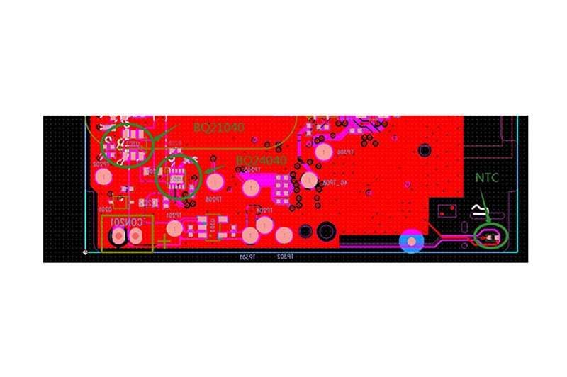
6. PCBA Protection Circuit (PCM) Specifications
Equipped with premium Japanese Seiko high-precision voltage detection IC to secure full operation life cycle.
6.1 Electrical Characteristics
| No. | Protection Parameter | Min | Typ. | Max. | Unit |
|---|---|---|---|---|---|
| 1 | Over-charge Protection Voltage | 4.260 | 4.280 | 4.300 | V |
| 2 | Over-charge Release Voltage | 4.030 | 4.080 | 4.130 | V |
| 3 | Over-charge Protection Delay Time | 0.7 | 1 | 1.3 | s |
| 4 | Over-discharge Protection Voltage | 2.950 | 3.000 | 3.050 | V |
| 5 | Over-discharge Release Voltage | 2.900 | 3.000 | 3.100 | V |
| 6 | Over-discharge Protection Delay Time | 179 | 256 | 333 | ms |
| 7 | Over-current Protection for Discharge | 1 | 1.8 | 2.5 | A |
| 8 | Internal Resistance | / | 45 | 60 | mΩ |
| 9 | Operation Static Current | 1.5 | 5 | 8 | μA |
| 10 | Current Consumption (Power Down) | / | / | 0.5 | μA |
| 11 | Short Circuit Protection | Available (Auto-recovery) | – | ||
| 12 | Short Circuit Protection Delay Time | 196 | 280 | 364 | μs |
6.2 PCBA Parts List & Bill of Materials (BOM)
| No. | Location | Part Name | Specification Description | Package | Qty | Brand/Note |
|---|---|---|---|---|---|---|
| 1 | U1 | Protection IC | S8261DAA-M6T1U | SOT23-6 | 1 | Seiko (Japan) |
| 2 | U2 | MOSFET | 8205 Dual Channel | SOT23-6 | 1 | VTC PCM Dept |
| 3 | R1 | Resistor | 330 Ω ± 5% | 0402 | 1 | Yageo |
| 4 | R2 | Resistor | 1.0 KΩ ± 5% | 0402 | 1 | Yageo |
| 5 | C1 | Capacitor | 0.1 μF ± 10% (50V) | 0402 | 1 | Murata |
| 6 | PCB | Printed Circuit | LP502025 Standard Board (Green) | 16.5×3.8×0.6mm | 1 | FR4 RoHS Compliant |
7. Storage and Battery Safety Cautions
Proper cell management guarantees prolonged lifecycle performance and safeguards against field hazards.
7.1 Storage Temperature Thresholds
| No. | Storage Duration | Allowable Temp. | Recommended Storage Humidity |
|---|---|---|---|
| 1 | Short Term (≤ 1 month) | -20 ~ 45 °C | 65 ± 20% RH (Non-condensing environment) |
| 2 | Medium Term (≤ 3 months) | -20 ~ 35 °C | |
| 3 | Long Term (≤ 1 year) | 0 ~ 25 °C |
7.2 Safety Instructions & Hazard Mitigation
- ◆
Charging Profile: Never charge the battery beyond the maximum voltage of 4.25V. Reverse charging is strictly prohibited. - ◆
Discharge Handling: Do not force discharge past 3.0V. Avoid short-circuiting the positive (+) and negative (-) gold-plated wire leads. - ◆
Mechanical Cautions: Do not crush, puncture, incinerate, open, drop, or solder directly onto the cell casing wrapper. - ◆
Do not deploy the battery inside heavy static-charge or high electromagnetic fields to prevent damaging the PCM circuit. - ◆
If electrolyte leakage occurs and contacts eyes, do not rub. Immediately flush eyes with running water and seek emergency medical aid. - ◆
If the cell emits odors, thermal heat, discoloration, swelling, or deformation during charging or use, terminate charging and isolate the cell immediately.
B2B Custom Assembly & Direct Wholesale
VTC Power provides comprehensive OEM/ODM custom solutions for the VTC-LP502025. Contact our engineering team for custom wire harness design, connectors (JST, Molex, Hirose), NTC thermistors, and high-performance safety PCM integration.