Technical insight
Product and application details
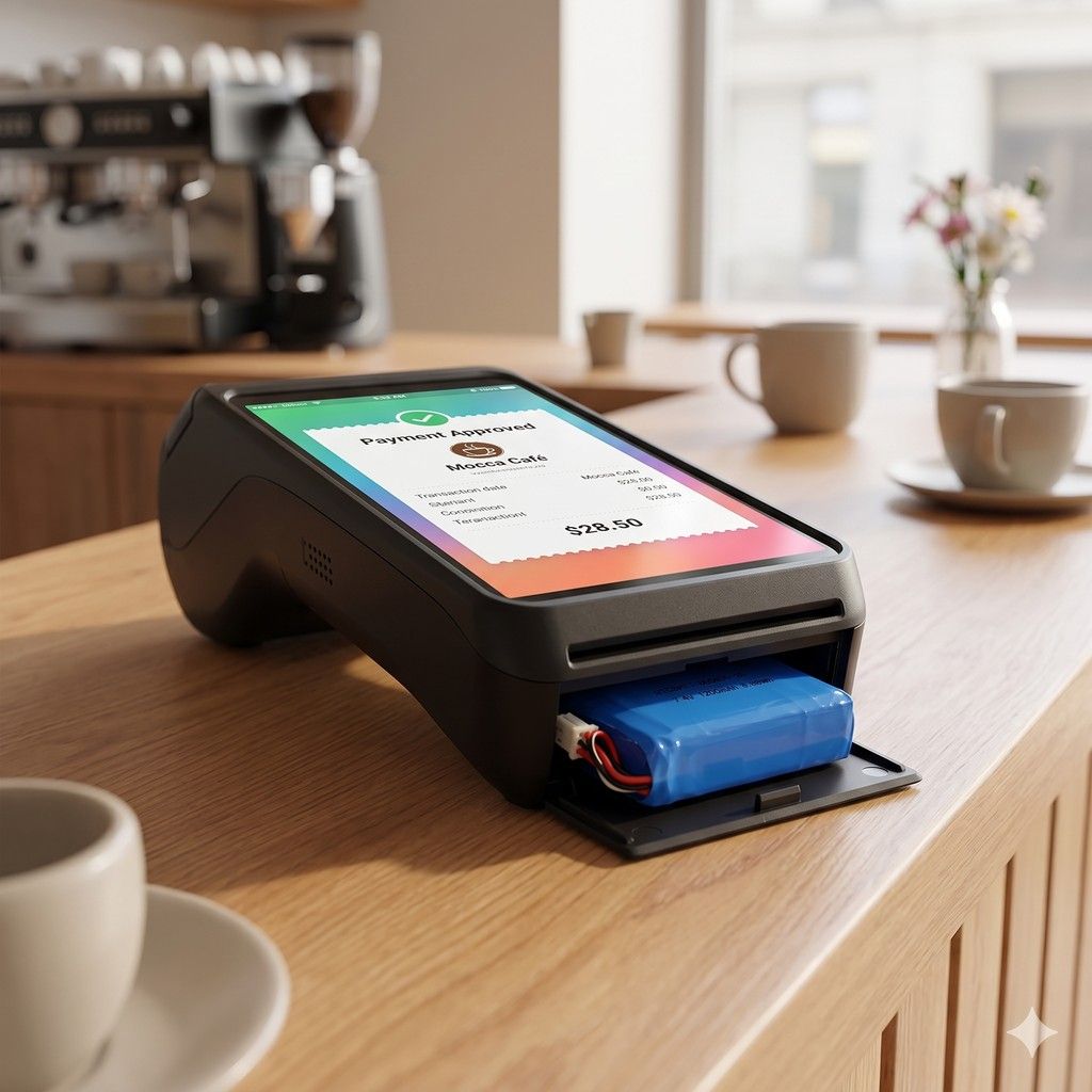
Handheld POS Terminal
Its 50g weight reduces operator fatigue during long shifts while the 1200mAh capacity sustains all-day scanning.
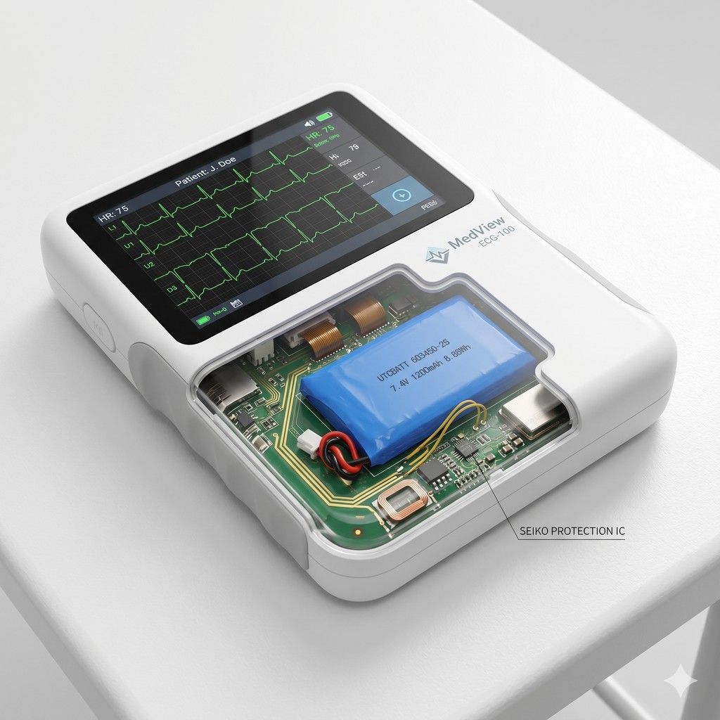
Portable Medical Monitor
The 12.5mm thickness allows seamless integration into compact casings while ensuring consistent 7.4V output for sensitive sensors.
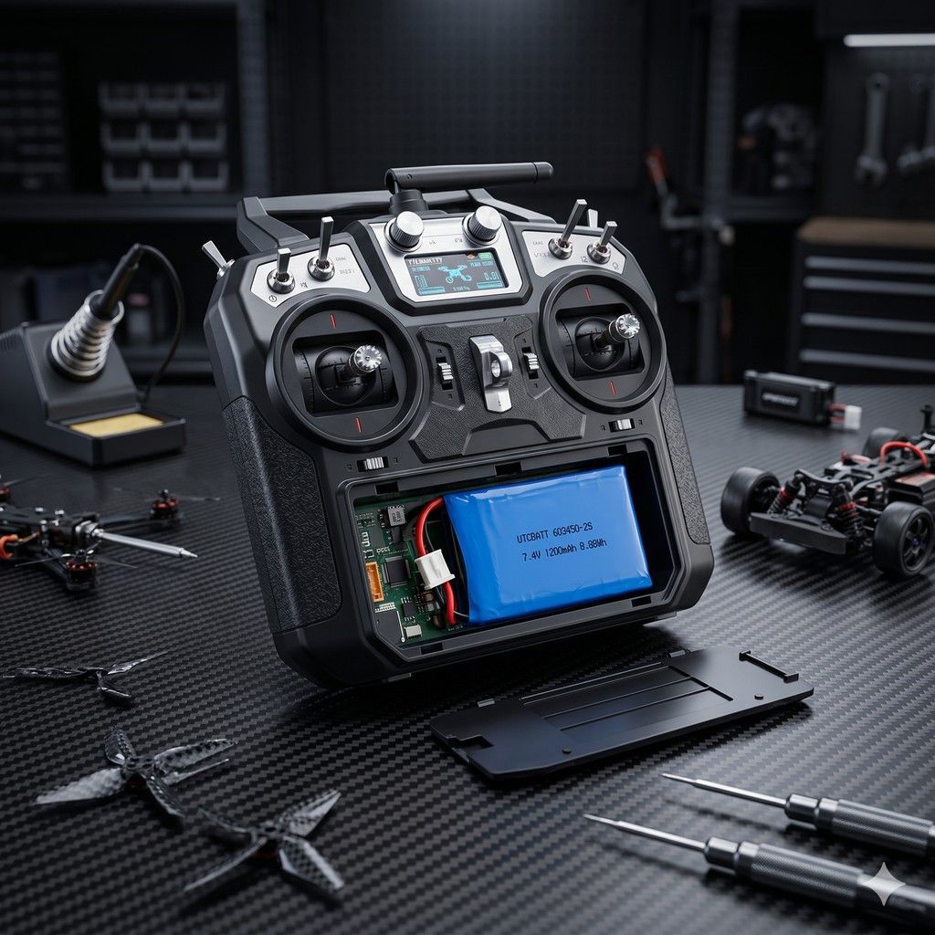
RC Hobby Controller
Operating reliably from -20℃ to 60℃, this battery maintains performance in extreme outdoor environments for precise control.
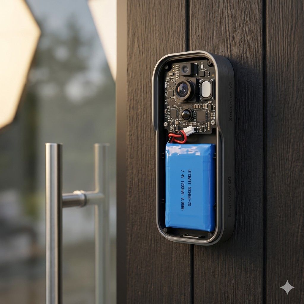
Smart Video Doorbell
The 52mm length fits narrow doorframe profiles while providing sufficient 1200mAh capacity for frequent motion-triggered video uploads.
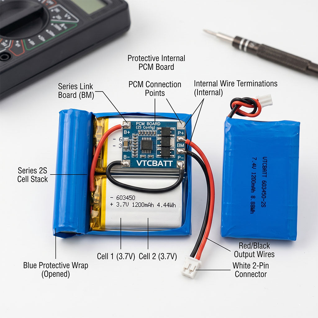
7.4V 1200mAh LP603450 2S Lithium-ion Polymer Rechargeable Battery Pack High-performance 2S series lithium polymer battery pack. Fully customized and engineered with high-density chemistry cells, a specialized series safety PCBA, integrated Seiko protection ICs, dual-MOSFET safety circuits, and 10K NTC thermistor. Optimized for premium IoT terminals, portable equipment, smart home sensors, and outdoor electronic systems. Product Visual Representation 1. Scope & Product Specification This technical datasheet describes the parameters and testing standards for the 7.4V Lithium-ion Polymer Series Rechargeable Battery Pack, model VTC-LP603450-2S , manufactured and supplied by VTC Power Co., Ltd. This series-connected battery pack uses two premium 3.7V LP603450

1. Scope & Product Specification
This technical datasheet describes the parameters and testing standards for the 7.4V Lithium-ion Polymer Series Rechargeable Battery Pack, model VTC-LP603450-2S, manufactured and supplied by VTC Power Co., Ltd.
This series-connected battery pack uses two premium 3.7V LP603450 cells to deliver a stable 7.4V nominal voltage. It features an advanced series protective PCM, precise Seiko control electronics, customized lead-out wires, a 10K NTC temperature sensor, and a JST miniature connection interface to satisfy rigorous B2B commercial standards.
2. Drawing of Cell & Battery Pack Dimensions
Mechanical dimensions define the cell parameters and battery pack constraints. Standard tolerances apply.
| Item | Description | Specification / Dimension |
|---|---|---|
| A | Cell Tab Length | 4 ~ 8 mm |
| B | Cell Tab Pitch | 12 ± 1.5 mm |
| C | Cell Tab Width | 3 ± 0.2 mm |
| D | Cell Top Sealant Length | 4 ± 1 mm |
| T (Cell) | Cell Thickness (Max) | Initial: 6.0 mm | After 600 cycles: 6.4 mm |
| W (Cell) | Cell Width (Max) | 34.0 mm |
| H (Cell) | Cell Height (Max) | 50.0 mm |
| T (Pack) | Battery Pack Thickness (Max) | 12.5 mm |
| W (Pack) | Battery Pack Width (Max) | 34.5 mm |
| H (Pack) | Battery Pack Height (Max) | 52.5 mm |
| L | Wire Length | 52 ± 3 mm (UL1571 28AWG) |
3. Basic Performance Specifications
All parameters are measured at a standard temperature of 15~35°C, relative humidity 45~85%RH, and atmospheric pressure of 86~106KPa.
| NO. | Technical Parameter | Specification Value | Test Conditions / Notes |
|---|---|---|---|
| 1 | Rated Capacity | 1200 mAh | 0.2C discharge |
| 2 | Nominal Capacity | 1100 mAh | 0.2C discharge |
| 3 | Minimum Capacity | 1060 mAh | 0.2C discharge |
| 4 | Weight | ≈ 40 g | Approximate battery pack weight |
| 5 | Initial Impedance | ≤ 200 mΩ | AC 1KHz measured |
| 6 | Normal Voltage | 7.4 V | Standard operating voltage (2S pack) |
| 7 | Initial Voltage | ≥ 7.6 V | Voltage within 15 days of factory shipment |
| 8 | Limited Charge Voltage | 8.4 V | Maximum charging termination limit for 2S series |
| 9 | Standard Charging Method | 0.2C CC current charge to 8.4V, then CV charge till current declines to 0.01C | |
| 10 | Cut-off Voltage | 6.0 V | Load voltage when discharge is terminated |
| 11 | Standard Charging Current | 220 mA | CC charge to limited voltage, then CV charge |
| 12 | Standard Charging Time | 6 ~ 7 hours | CC-CV charge profile |
| 13 | Rapid Charging Current | 1100 mA | 1.0C rate rapid charging current |
| 14 | Rapid Charging Time | 1.5 hours | Fast charge profile |
| 15 | Standard Discharging Current | 220 mA | CC discharge to cut-off voltage |
| 16 | Max. Discharging Current | 1100 mA | 1.0C rate continuous discharge |
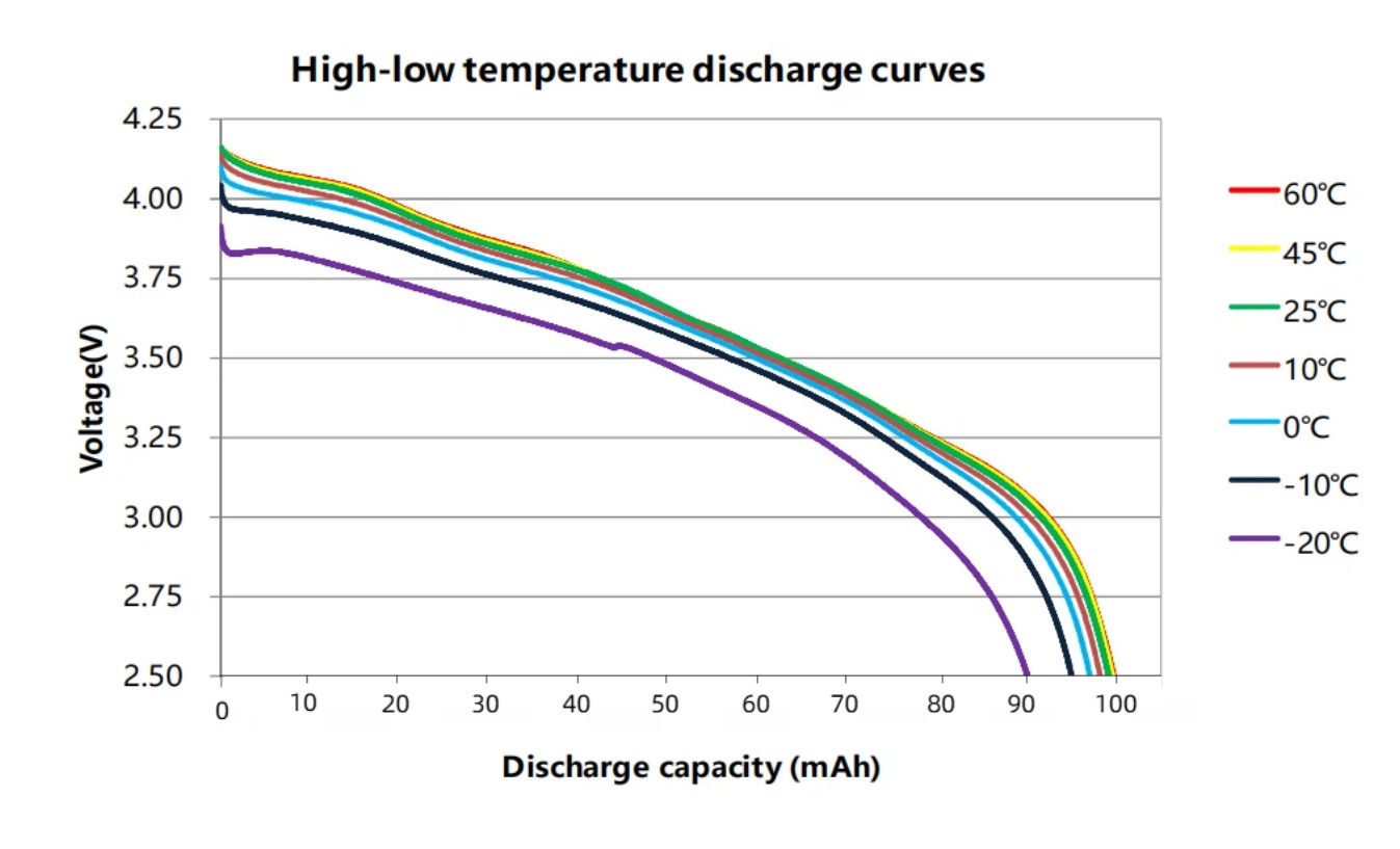
| 17 | Operating Temperature | Charge: 0 ~ 60 °C Discharge: -20 ~ 80 °C |
Operating environment constraints |
| 18 | Operating Humidity Range | ≤ 90% RH | Non-condensing environment |
4. Electrochemical & Environmental Characteristics
Strict criteria applied during environmental qualification testing:
| No. | Test Item | Performance Criterion | Standardized Test Method |
|---|---|---|---|
| 1 | 0.2C Discharge Capacity | Discharging capacity is not less than normal capacity (1100 mAh) | After standard charging, rest 5 minutes, then discharge at 0.2C to cut-off voltage. |
| 2 | 1.0C Discharge Capacity | Discharging capacity is not less than 90% of normal capacity | After standard charging, rest 5 minutes, then discharge at 1.0C to cut-off voltage. |
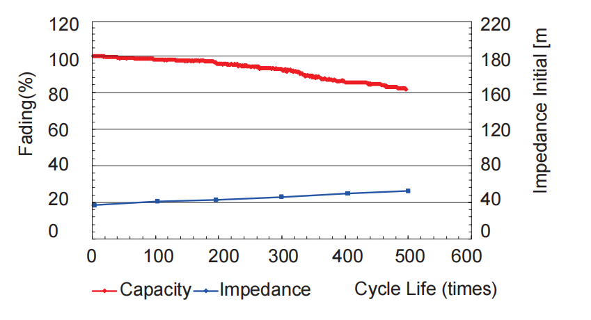
| 3 | Cycle Life | ≥ 600 cycles | Charge: 0.2C CC-CV to limited voltage, current cut-off 0.02C. Discharge: 0.2C CC to cut-off voltage. Test terminates when capacity drops below 80% of rated capacity. |
| 4 | Self-discharge | Remaining capacity is ≥ 85% of initial capacity | After standard charging, store the cell for 28 days at 20 ± 5°C. Then discharge at 0.2C. |
| 5 | Constant Temp/Humidity | No explosion, no fire, no leakage. Capacity is ≥ 60% of initial capacity. |
Standard charged cell stored for 48 hours at 40 ± 5°C and 90~95% RH. Then discharge at 1.0C. |
| 6 | Vibration Test | No explosion, no fire, no leakage. | Subject to 30 min vibration per axis (X, Y, Z). Freq: 10~30Hz, Amp: 0.38mm. Freq: 30~55Hz, Amp: 0.19mm. Rate: 1 oct/min. |
| 7 | Shock Test | No explosion, no fire, no leakage. | Acceleration: 100 m/s² (10G). Pulse duration: < 16 ms. Shock cycles: 2100 ± 10 times. |
5. Safety Characteristics
Note: Safety assessments are performed under strictly controlled test parameters using protective enclosures.
| No. | Safety Test | Pass Criterion | Test Conditions |
|---|---|---|---|
| 1 | Overcharge Test | No explosion, no fire | Discharge cell at 1.0C to cut-off voltage. Then charge at 1.0C continuously for 2.5 hours. |
| 2 | Short-circuit Test | No explosion, no fire | Standard charged cell is short-circuited externally with copper wire (resistance ≤ 80mΩ). Test runs until cell temperature falls 10°C below the peak temperature. |
| 3 | Thermal Test (Hot Box) | No explosion, no fire | Standard charged cell placed in hot box. Temp ramp: 5 ± 2°C/min. Termination temperature: 130 ± 2°C. Heat sustained for 30 minutes. |
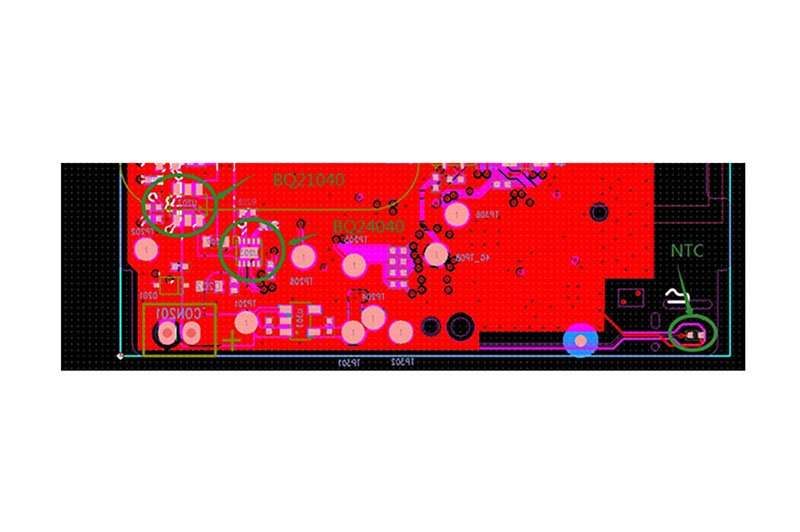
6. PCBA Protection Circuit (PCM) Specifications
Equipped with premium Japanese Seiko high-precision voltage detection IC to secure full operation life cycle.
6.1 Electrical Characteristics
| No. | Protection Parameter | Min | Typ. | Max. | Unit |
|---|---|---|---|---|---|
| 1 | Over-charge Protection Voltage | 4.260 | 4.280 | 4.300 | V |
| 2 | Over-charge Release Voltage | 4.130 | 4.180 | 4.230 | V |
| 3 | Over-charge Protection Delay Time | 0.7 | 1 | 1.3 | s |
| 4 | Over-discharge Protection Voltage | 2.950 | 3.000 | 3.050 | V |
| 5 | Over-discharge Release Voltage | 2.900 | 3.000 | 3.100 | V |
| 6 | Over-discharge Protection Delay Time | 179 | 256 | 333 | ms |
| 7 | Over-current Protection for Discharge | 3.0 | 4.0 | 5.0 | A |
| 8 | Internal Resistance | / | 45 | 60 | mΩ |
| 9 | Operation Static Current | 3 | 5 | 7 | μA |
| 10 | Current Consumption (Power Down) | / | / | 0.5 | μA |
| 11 | Short Circuit Protection | Available (Auto-recovery) | – | ||
| 12 | Short Circuit Protection Delay Time | 196 | 280 | 364 | μs |
6.2 PCBA Parts List & Bill of Materials (BOM)
| No. | Location | Part Name | Specification Description | Package | Qty | Brand/Note |
|---|---|---|---|---|---|---|
| 1 | U1 | Protection IC | S8261DAI-M6T1U (Seiko IC) | SOT23-6 | 1 | Seiko (Japan) |
| 2 | U2 | MOSFET | dp8205 Dual Channel MOSFET | TSSOP-8 | 1 | DP MOSFET Dept |
| 3 | R1 | Resistor | 330 Ω ± 5% | 0603 | 1 | Yageo |
| 4 | R2 | Resistor | 470 Ω ± 5% | 0603 | 1 | Yageo |
| 5 | R3 | NTC Resistor | 10K Ω ± 1%, B3435 ± 1% | 0603 | 1 | 10K NTC |
| 6 | C1 | Capacitor | 0.1 μF / 25V ± 5% | 0603 | 1 | Murata |
| 7 | PCB | Printed Circuit | LP603450 Standard Board | / | 1 | FR4 RoHS Compliant |
7. Battery Pack Component Details
Bill of materials used for pack housing and interface connectors.
| No. | Component | Qty | Material Details / Specifications |
|---|---|---|---|
| 1 | LiPo Cell | 1 | VTC-LP603450 | 1200mAh Li-ion polymer cell |
| 2 | PCM Circuit | 1 | Fiber glass polymer compound circuit board (Pass RoHS) |
| 3 | Wire Leads | 3 | UL1571 28AWG Polythene and copper wires |
| 4 | Connector | 1 | JST-1.0-3P Connector (PA66, UL94V-0, White) |
8. Storage and Battery Safety Cautions
Proper cell management guarantees prolonged lifecycle performance and safeguards against field hazards.
8.1 Storage Temperature Thresholds
| No. | Storage Duration | Allowable Temp. | Recommended Storage Humidity |
|---|---|---|---|
| 1 | Short Term (≤ 1 month) | -20 ~ 45 °C | 65 ± 20% RH (Non-condensing environment) |
| 2 | Medium/Long Term (≤ 3 months) | -10 ~ 45 °C | |
| 3 | Recommended Storage | 15 ~ 35 °C |
8.2 Safety Instructions & Hazard Mitigation
- ◆
Charging Profile: Never charge the battery beyond the maximum voltage of 8.4 V. Reverse charging is strictly prohibited. - ◆
Discharge Handling: Do not force discharge past 6.0 V. Avoid short-circuiting the positive (+) and negative (-) gold-plated wire leads. - ◆
Mechanical Cautions: Do not crush, puncture, incinerate, open, drop, or solder directly onto the cell casing wrapper. - ◆
Do not deploy the battery inside heavy static-charge or high electromagnetic fields to prevent damaging the PCM circuit. - ◆
If electrolyte leakage occurs and contacts eyes, do not rub. Immediately flush eyes with running water and seek emergency medical aid. - ◆
If the cell emits odors, thermal heat, discoloration, swelling, or deformation during charging or use, terminate charging and isolate the cell immediately.
B2B Custom Assembly & Direct Wholesale
VTC Power provides comprehensive OEM/ODM custom solutions for the VTC-LP603450-2S. Contact our engineering team for custom wire harness design, connectors (JST, Molex, Hirose), NTC thermistors, and high-performance safety PCM integration.